The CUBE Installation Guide
This guide describes the considerations for installing the CUBE.
General Information
Do not attempt to open or to disassemble the chassis (enclosure) of the CUBE. Please contact your dealer for service from a qualified technician.
Do not install the CUBE in a location where it is exposed to:
- Heating sources, such as stoves, ovens, heaters, radiators or heating air ducts
- Direct contact from sunlight
- Rain or moisture
- Excessive dust accumulation
- High humidity
- Mechanical movement, vibration or shock
- Strong magnets or magnetic fields or magnetically unshielded speakers
- Ambient temperature of more than 95 ° F (35 ° C) or less than 32 ° F (0 ° C)
Important
The CUBE should be installed in an environment which maintains a reasonable ambient room temperature – for instance, approximately 20 to 22 ° C (68 to 72 ° F).
The CUBE must be installed to allow for adequate air flow around it. Air flow around the cooling fins should not be unduly hampered.
It is recommended to leave a clearance of at least 8 inches (20cm) behind the sides and back panel of the CUBE, as illustrated below.
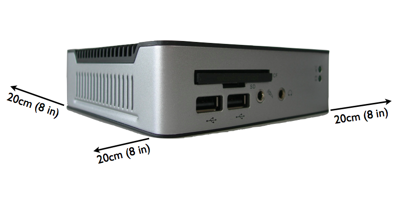
Recommended minimum clearance around the CUBE
Mounting the CUBE
The CUBE should ideally be mounted with the cooling fins facing toward free air, to allow for the best possible ventilation around the CUBE.
For example, if the CUBE is mounted against a wall or on a shelf, it is recommended that the footplate (where the serial number label can be found) faces toward the wall/shelf, with the cooling fins facing away from the wall and toward the free air.
If the CUBE is mounted vertically against a wall, it should always be mounted so that the length of the cooling fins run vertically. The CUBE’s connectors will therefore face to the left or right (instead of to the top or bottom). This facilitates the convective flow of air along the cooling ducts.
Note
We do not recommend wall-mounted installations with the connectors facing up or down, as the cooling fins will then be aligned horizontally, resulting in obstruction of the airflow.
Reverse Vertical Mount
Nonetheless, in some installations, it may be desirable to utilize the entire footplate as a visible area for branding or provider labels. This necessitates reverse-mounting to a wall, with the cooling fins facing toward the wall so that the entire bottom plate is available as a visible branding / label area.
For such installations, we recommend that:
- the CUBE MUST be installed with the cooling fins running vertically (ie, the connectors will be facing toward the left and right).
- the CUBE should be mounted to the wall with spacers, so that there is an air gap of at least 0.75in (2cm) between the wall and the cooling fins
- there should be a clearance of at least 8in (20cm) below the CUBE, and 12in (30cm) above the CUBE.
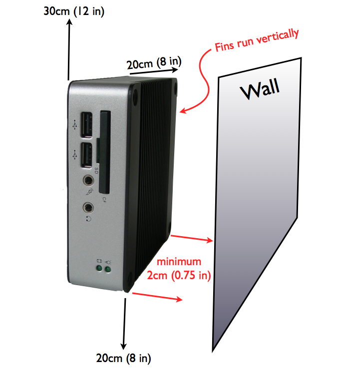
Recommended minimum clearances for a reverse vertical mount
These recommendations presume a room-temperature environment of approximately 22 ° C (72 ° F), with the walls at room temperature.
Other Mounting Configurations
The CUBE can also be mounted in many other configurations. If a bracket is used, the recommended clearances should still be maintained. For example, if a bracket is used with the reverse vertical mount, the bracket should not cause any airflow over the cooling fins to be restricted (this may necessitate using a spacer between the CUBE and the bracket).
The CUBE Audio Output
Audio is played out of the CUBE 3.5mm audio port (identified by a headphone symbol). This audio port is wired for the standard 3.5mm stereo “tip, ring, sleeve” jack:
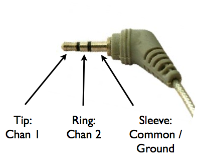
Audio Wiring
| Tip | Channel 1 (“Left”) |
| Ring | Channel 2 (“Right”) |
| Sleeve | Common / Ground |
The CUBE is normally provided with at least a default audio program being played on Channel 1 (“Left”) of the 3.5mm connection port. A stereo headphone can be connected to verify audio playback – the Channel 1 audio will be heard on the left earpiece.
The CUBE Audio Output Level
The CUBE is provided with the volume level initially set to 50%. This volume can be adjusted remotely. It is also possible to set the volume during installation by connecting a keyboard.
With the volume set to 100%, and when using “hot” audio (audio that remains close to the maximal 0dB digital level), typical output level will be 1.25Vrms when driving 32 Ω, 600 Ω, 3300 Ω, 10k Ω, etc.
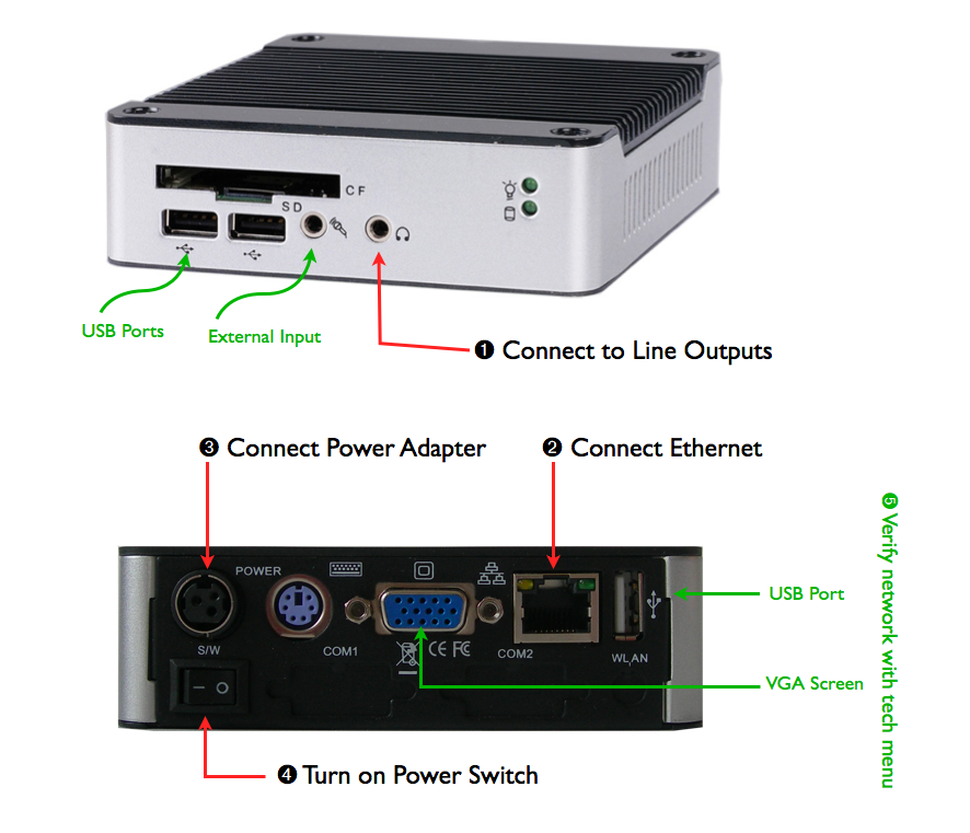
Connecting the CUBE
Connect the audio equipment at the premises to the CUBE’s audio output
Connect the CUBE’s ethernet RJ-45 port to the network
Connect the CUBE’s power adapter
- Turn on the CUBE
- 33A-style CUBEs have a power switch on the rear panel that must be turned on. 335MX-style CUBEs turn on automatically.
- The power LED on the CUBE will light up.
- During start up, the CUBE performs a sequence of Power-On Self Tests. 33A-style CUBEs will first emit two brief ascending tones, followed some seconds later by a further 3 ascending tones. Once the CUBE is ready to commence audio playback, it will emit 3 beeps of the same frequency. Audio should begin to play out shortly thereafter. The thinner 335MX-style CUBEs follow the same sequence, but do not emit any tones.
Network connectivity can now be verified using the on-board tech menu.
Important Information for MOH and Telephone Systems Installers
The audio output port of the CUBE is electrically similar to that of a CD player, iPod, PC, MP3 player, radio, satellite receiver, etc.
Such audio ports cannot be connected directly to so-called “wet loop” telecommunications ports, as damage may result to either piece of equipment.
A “wet loop” is a connection directly to a telecommunications port that carries DC voltage (e.g. the FXS connection from a PBX or switch to an analogue extension), or which may carry ring-signal voltage.
The CUBE should preferably be connected to a designated MOH input on the PBX / switch. To connect the CUBE to a wet loop, a proper barrier device (isolating transformer) must be used.
- On certain premises, installers may be unable to determine whether the provided pair is connected to the switch’s MOH input, or to a wet loop. We recommend in such cases that installers utilize a DC voltmeter to measure across the provided pair. If a DC voltage is measured, the provided pair is a wet loop, and an appropriate barrier device must be used.
- Some switches (e.g. Avaya) do not offer any MOH inputs, but require that MOH sources be wired up to a telecommunication line card instead. In such cases an appropriate barrier device must be used. See the switch’s guide (e.g. Avaya) for more information.
- Avaya documentation regarding the MOH connection can easily be misinterpreted. The Avaya guide contains two sections referring to connecting “FCC approved” vs “non-FCC approved” MOH source equipment. Since the CUBE carries FCC approvals, installers may incorrectly pick the first option. The Avaya reference here, however, pertains to FCC approval as a telecommunications (telephone) port (which is highly uncommon on MOH equipment), therefore the “non-FCC approved” section applies.
- If in doubt, follow the PBX / switch manufacturer’s instructions for connecting standard CD players, radios etc.
Important
Only approved telecommunications (telephone) ports may be connected to wet loops. To our knowledge, no MOH device on the market (barring those with actual phone jack outputs), have outputs approved as telecommunications ports. Connecting such MOH outputs directly to a wet loop risks damage to either piece of equipment, as well as deterioration of the audio quality.